
Step 1
Gather Supploes
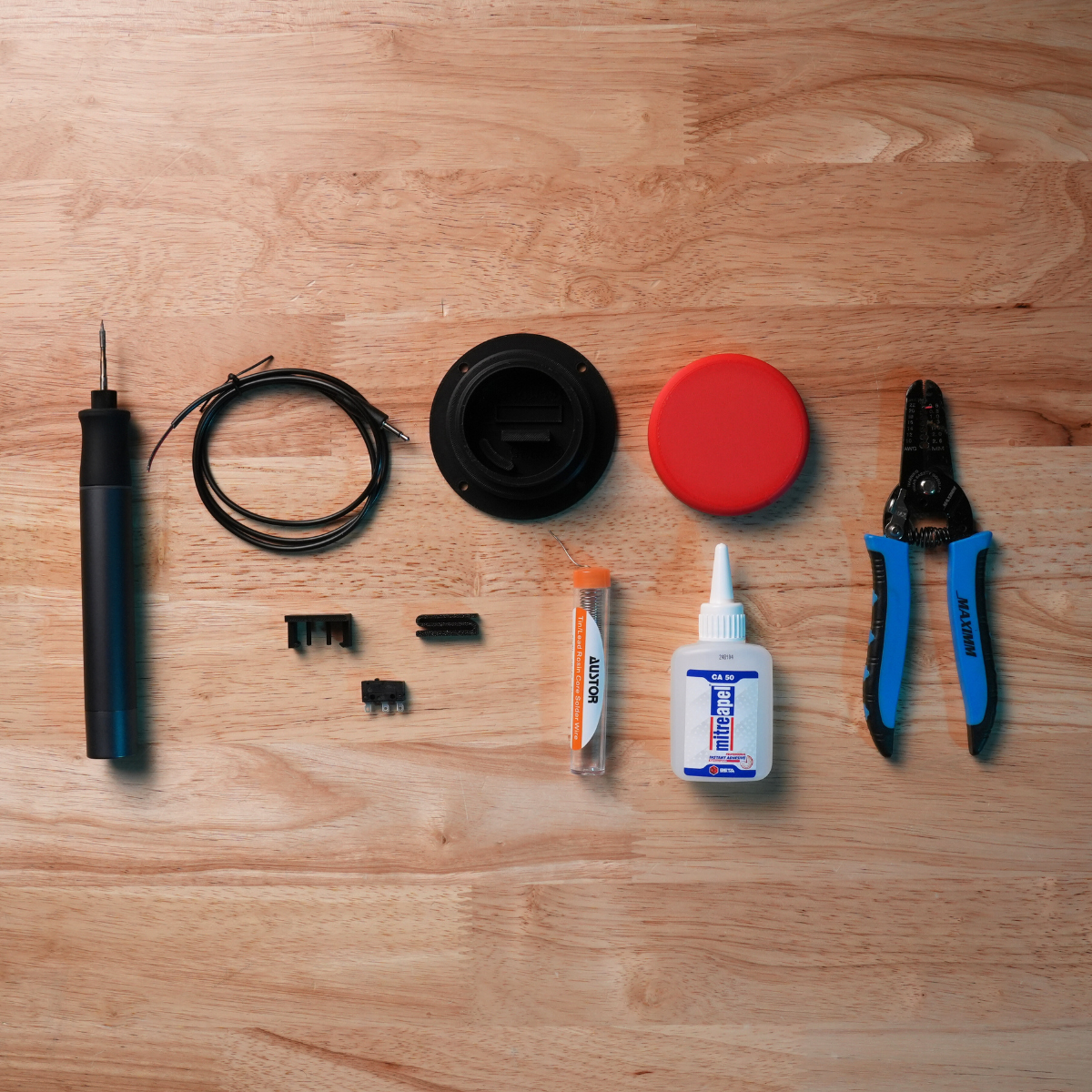
You will need the 3D printed top, base, limit switch clip and limit switch spring. You will also need a limit switch and a 3.5mm headphone cable. If you are assembling our standard switch kit all these parts are included.
You’ll also need wire strippers, super glue, solder, and a soldering iron.
If you’re missing any of these tools or materials, check out our curated list of Amazon links to the products we use and recommend.
Step 2
Prepare Your Headphone Cable
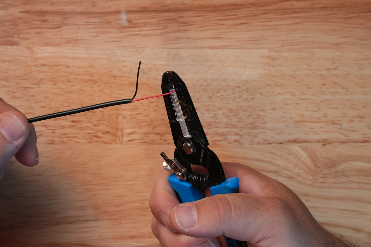
Insert the headphone cable through the hole in the base. Use wire strippers to remove about 1/2 inch of casing from each headphone wire.
Twist the ends of each wire to create two neat bundles—be sure there are no stray strands left loose.
Step 3
Solder Your Wires
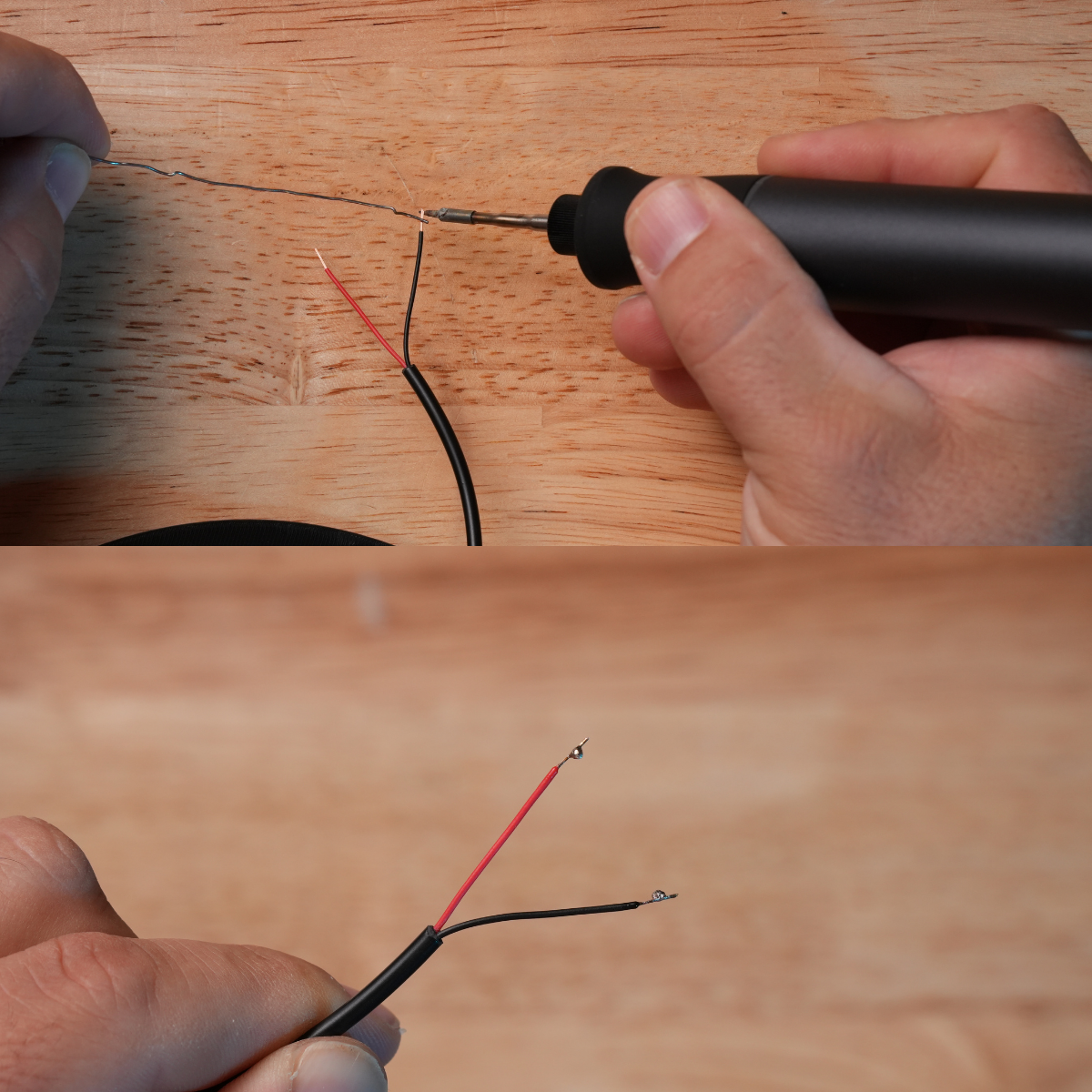
Apply a glob of solder to the end of each headphone jack wire. To do this, heat the exposed wire with the tip of your soldering iron. Then, feed solder onto the heated wire until it begins to melt. Continue feeding solder until a small glob forms at the end of the wire.
Step 4
Solder Wires to the Limit Switch
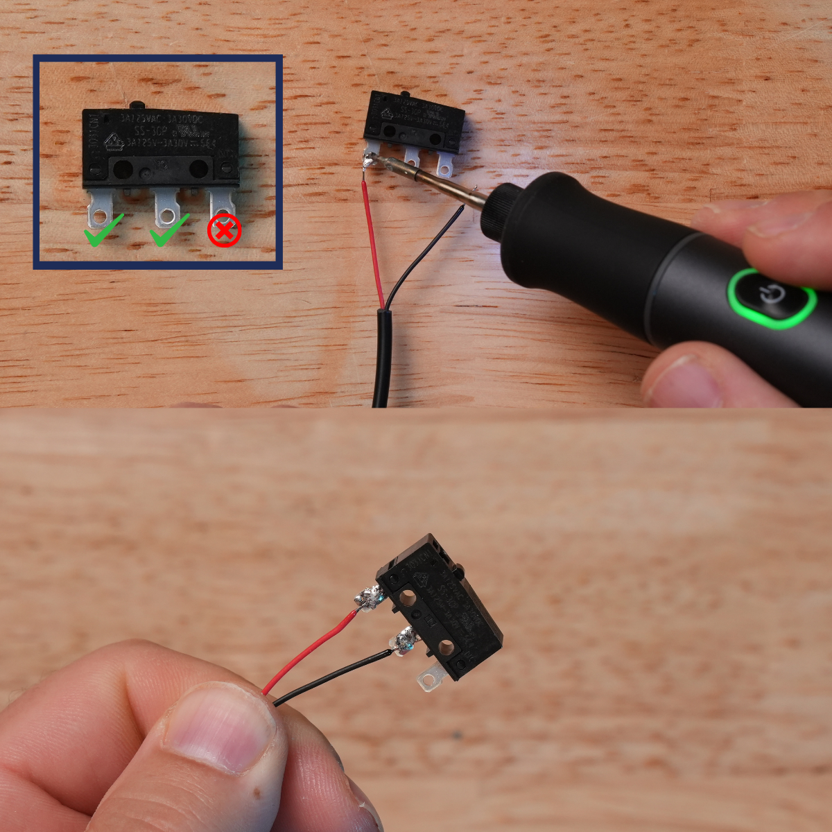
Place the wire and solder glob onto the leads shown in the picture. Use the soldering iron to heat the solder until it melts and bonds to the limit switch lead. It doesn’t matter which wire goes to which lead—just make sure not to solder any wire to the lead marked with an “X” in the picture.
Once soldered, give each wire a gentle tug to ensure it’s securely attached to the limit switch.
Step 5
Attach the Limit Switch
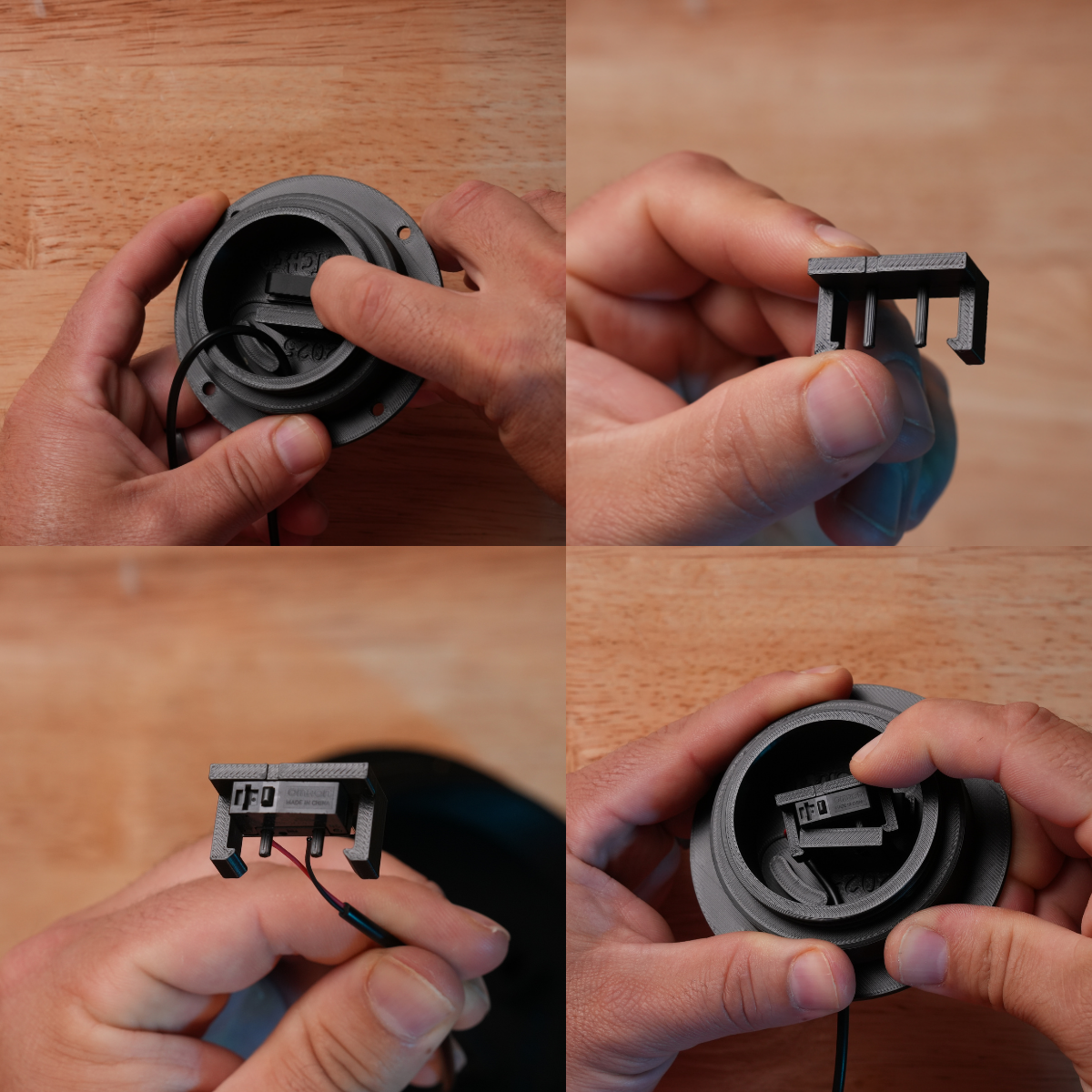
Insert the limit switch spring into the base.
Orient the limit switch clip so that the notch on its edge aligns with the button on the limit switch. Press the holes of the limit switch onto the posts of the clip.
To secure the clip to the base, press down on the limit switch spring with the bottom of the clip. Hook one end of the clip onto the mounting wall of the base. Make sure the cord follows the engraved path in the base. Then gently press the opposite end of the clip until it snaps into place.
Ensure that your wires are not pinched by the clip or spring. If assembled correctly, the limit switch should depress slightly when pressed and return to its original position when released.
Step 6
Secure the Cable
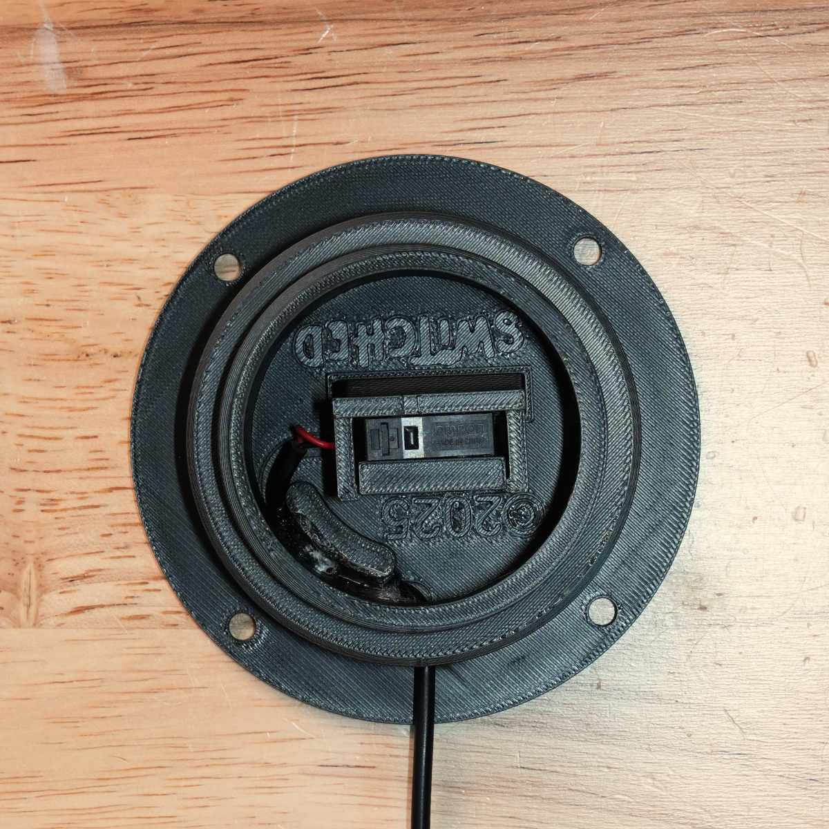
Route the cable through the cable capture slot and press it firmly into place. This helps prevent the wire from being pulled and damaging the switch. Apply a small amount of super glue to the cable to lock it into place. Allow the glue to dry completely before continuing.
Step 7
Secure the Top
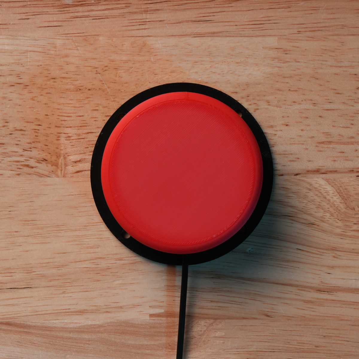
Insert the three top springs into the corresponding mounts in the base. Be careful to press the springs into place by applying pressure only to the base of each spring—avoid bending or deforming them.
Next, thread the top onto the base. Once the threading has started, continue tightening the top while gently pulling upward on it. This helps release any rotational stress on the top springs.
Finally, test your switch by plugging it into an adapted toy or device to make sure everything is working correctly.